
ELECTRICAL
Earthpit Testing
The main reason for doing earthing in electrical networks is for safety. When all metallic parts in electrical equipment are grounded, if the insulation inside the equipment fails, there are no dangerous voltages in the equipment case. If the live wire touches the ground then the circuit is effectively shorted and the fuse/breaker will immediately trip. When the breaker/fuse is tripped then the dangerous voltages are away.
Purpose of Earthing:
Safety for Human Life/ Building/Equipment
To save human life from danger of electrical shock or death by blowing a fuse i.e. To provide an alternative path for the fault current to flow so that it will not endanger the user
To protect buildings, machinery & appliances under fault conditions.
To ensure that all exposed conductive parts do not reach a dangerous potential.
To provide a safe path to dissipate lightning and short circuit currents.
To provide a stable platform for the operation of sensitive electronic equipment e. To maintain the voltage at any part of an electrical system at a known value to prevent overcurrent or excessive voltage on the appliances or equipment.
Over voltage protection: Lightning, line surges, or unintentional contact with higher voltage lines can cause dangerously high voltages to the electrical distribution system. Earthing provides an alternative path around the electrical system to minimize damage to the System.
Voltage stabilization: There are many sources of electricity. Every transformer can be considered a separate source. If there were not a common reference point for all these voltage sources it would be extremely difficult to calculate their relationships to each other. The earth is the most omnipresent conductive surface, and so it was adopted in the very beginnings of electrical distribution systems as a nearly universal standard for all electric systems.
Facilities Support
Nowadays, earth pits are the preferred method for earthing, especially for electrical networks. Electricity always follows the path of least resistance, and to divert the maximum current away from a circuit, earthing pits are designed to reduce ground resistance, ideally to 1 ohm.
To achieve this: An area of 1.5m X 1.5m is excavated to a depth of 3m. The pit is half filled with a mixture of wood coal powder, sand, and salt. A 500mm X 500mm X10mm GI plate (earth plate) is placed in the middle Connections between the earth plate and the surface are installed for system earthing.
The rest of the pit is filled with the coal/sand/salt mixture. To connect the earth plate to the surface, two GI strips with a cross-section of 30mm X 10mm can be used, but a 2.5” GI pipe with a flange at the top is preferable. Additionally, the top of the pipe can be covered with a T-section, to prevent mud and dust from entering and clogging the pipe. In summer, the pit should be watered to keep it from drying out.
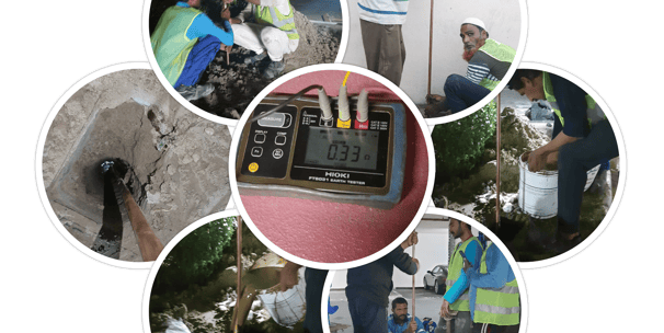
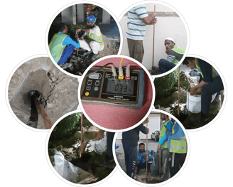
Constructing and Maintaining an Earth-Pit:
Wood coal powder is a great conductor and prevents corrosion of the metal parts The salt dissolves in water easily, increasing conductivity significantly Sand allows water to percolate through the entire pit To test the effectiveness of the pit, check that the voltage difference between the pit and the neutral of the mains supply is less than 2 volts. The resistance of the pit should be maintained at under 1 ohm, up to a distance of 15m from the conductor.
Advantages of the earth-pit method include:


The resistance of the earthing system is affected by a variety of factors: Soil Resistance – The composition of the soil, grain size, and distribution.
Moisture – Up to 15% water content significantly changes resistivity. Beyond that, it has little effect. Dissolved Salts – Pure water has very low conductivity. Salt is an electrolyte that reduces the resistance when it’s dissolved in water. Obstructions – Nearby concrete buildings or rocks in the soil underneath the earthing system can increase its resistance. Current Magnitude – Long periods of exposure or higher currents flowing through the earth can dry the soil in the surrounding area and increase the system’s resistance.
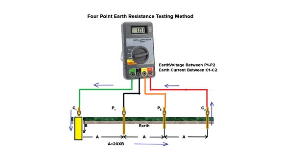
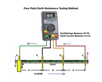
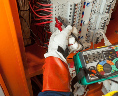
Measuring Earth Resistance Earth resistance is measured with an earth tester, also called a ‘megger’, which can test the resistance across a range of currents and distances. It consists of a voltage source, an ohm-meter to measure resistance, and spikes that are staked into the ground for measuring. You can measure the soil resistance using either the 3-point method or the 4-point method.
Earth Resistivity:
Facilities Support
Earth Fault Loop Impedance Test
During an electrical fault on a circuit, a current will flow from the Line conductor towards Earth and into the Neutral point of the supply company transformer.
This circuit (loop), which consists of all the elements within the loop (supply transformer winding, supply company phase conductor, main fuse, main switch, protective device, Line conductor, the fault, Earth conductor, main earth terminal, supply company earthing conductor) is the Earth Fault Loop. Its impedance is the measured value in Ohms.
To ensure the operation of the protective devices within the installation (such as MCBs), the Earth Fault Loop Impedance value must be measured at the furthest point of the circuit and compared with the requirements found in BS 7671. If the measured value is higher than it is allowed in BS 7671, then the circuit is not safe.
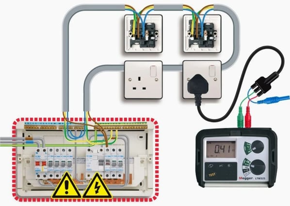
The External Earth Fault Loop test sequence:
Step 1. Use an Earth Fault Loop Tester or select the Earth Fault Loop Test option on a multifunctional tester such as the Megger 1553.
Step 2. Test on the incoming side of the installation. Connect one test lead to the Line terminal, the second test lead to the Neutral terminal, and the third (usually green) test lead to the incoming Earth conductor.
Step 3. Press the TEST button. The measurement should be a low reading ohm value. Do not forget to record this value of `Ze` on the Electrical Installation Certificate.
How to test the highest Earth Fault Loop Impedance (Zs)?
Having obtained the `Ze` value for the installation, the value of `Zs` can be easily calculated for every circuit. During the City and Guilds 2391 practical assessment it is allowed to test every circuit for the value of `Zs`; however, because of the limited time at hand it is advised to calculate the value of `Zs` instead of direct measurement.
The formula for determining `Zs:
Zs=Ze + (R1+R2)
Zs – earth fault loop impedance of the circuit tested
Ze – earth fault loop impedance external to the supply
(R1+R2) – Summation of the resistance of Line and Earth for the tested circuit.
The Earth Fault Loop test sequence:
Step 1. Locate the furthest point on the circuit to be tested (such as the furthest socket)
Step 2. With the appropriate Earth Fault Loop Tester, connect the test leads to the Line, Neutral, and Earth terminals.
Step 3. Measure and write down the test results on the Schedule Of Test Results.
Please note that if the circuit is RCD protected then you will have to select the “No trip” function of the Megger 1553 to avoid nuisance tripping of the RCD. If your tester does not have this option then you will have to link out the RCD.
Verification of test results
Having obtained the value of Zs for every circuit, you will be expected to verify that these values are within the accepted limits described by BS 7671.
Values of Zs should be compared with one of the following:
– The values in Appendix B of Guidance Note 3 for Inspection and Testing.
– Earth fault impedance figures provided by the designer.
– Tabulated values in BS 7671, corrected for temperature.
– Rule-of-thumb figures with tabulated values in BS 7671.
In our guide for the Inspection and Testing practical assessment, we advise using the fastest method which is the last one of the above described.
Rule-of-thumb method The highest measured Zs value for each circuit should not exceed 0.8 of the relevant value in the BS 7671 tables.
In other words, select the appropriate value from the tables in BS 7671 and multiply it by 0.8. This number should be higher than the highest measured Zs value for the given circuit.
Facilities Support
How often do we need to undertake PAT testing?
The frequency with which you need to inspect and test your electrical appliances depends on the type of equipment and the environment in which it is used. For example, a power tool that is used daily on a construction site would need to be checked more often than a TV in a hotel room.
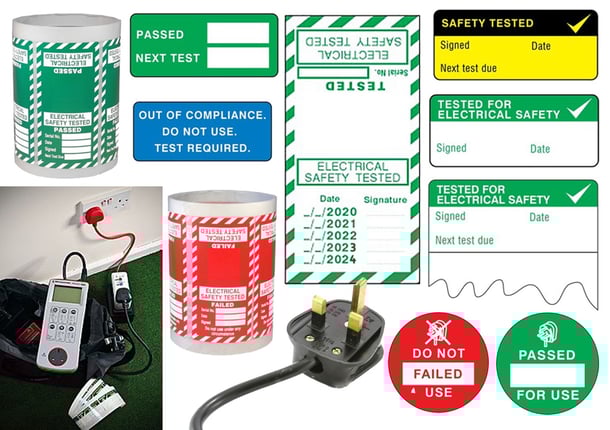
What is PAT Testing?:
Portable Appliance testing or PAT testing is the process of examining an electrical appliance to ensure it is safe for use. Most defects are visually identifiable but others can only be found with rigorous testing. We use a combination of visual inspection and testing to examine an appliance. We are looking for electrical flaws, damaged cables, and whether the item is fit for purpose.
Why do we need it?
It is important to have formal inspections of items at regular intervals, as day-to-day use of portable electrical appliances inevitably causes wear and tear to leads and plugs. If defects go undetected this could result in an electric shock or fire.
Employers, institutions, and landlords have a statutory responsibility to ensure all electrical appliances used by employees, guests or tenants are safe.
Facilities Support
RCD Test
What is an RCD?
RCD stands for Residual Current Device. In short, an RCD is an electrical protection device that disconnects a circuit in the event of a fault.
The Residual Current Device operates on the principle of continuously monitoring the balance of currents between the Line conductor and the Neutral conductor. If this balance is lost that means that the current from the Line conductor is going somewhere else other than the Neutral conductor – that is to Earth, through a fault somewhere within the installation.
A regular domestic RCD is set to a 30mA limit. The reason for this is that the human body can withstand a current of that level. Anything above this would be dangerous for life, so the RCD would cut the supply off.
How to perform an RCD test?
This is a live test so extra care is advised!
Step 1. Use a dedicated RCD test meter or the RCD function of a multifunctional tester such as the Megger 1553. Make sure that the installation is fully energized.
Step 2. Connect the test leads on Line, Neutral, and Earth terminals anywhere on the installation but after the RCD (i.e. socket).
Step 3. Testing should be done with 50% In, 100% In, and 500% In on both 0° and 180°. Depending on your test meter, this could be done automatically or manually. Please refer to the user instructions of your RCD tester.
Facilities Support
Field Contracting
Electrical Installation for LV system
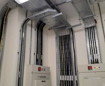
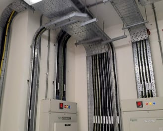
Electrical installation forms the foundation of our contracting division team with its success primarily due to a professional operations & management team that is well supported by our driven and motivated staff. Our core business is to focus on the delivery of turnkey project services to our clients. Our project services include supply, site installation, Cabling, LV Equipment Installation, Commissioning, Testing, and project management across a range of industry sectors.
From the Project Concept stage we assess the characteristics of the installation, and based on the client’s plant and equipment requirements, determine load and propose suitable protection systems, carry out cable calculations, and engineer the associated control systems. Using AutoCAD all construction drawings comprising of general arrangements, wiring looping layouts, single line diagrams, and load schedules are given to the worksite for the installation phase.
Field Contracting
Electrical Fitout Works
Supply and Installation of electrical systems in workspace/Office, where the base construction/shell & core is completed by the landlord.
Obtain DEWA NOC for additional Power Load upgrades where the existing load is not sufficient. Obtain DEWA approval for Fit-out office merging/separation.
Field Contracting
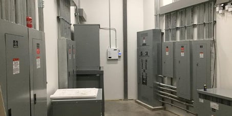
Retrofitting & Refurbishment of LV Switchgear System
When To Retrofit, Refurbish, or Replace Ageing Switchgear
Management and maintenance of aging switchgear is always a challenging task. Older buildings are being upgraded to the 21st century, or new buildings have additional power demand, meaning existing equipment needs to be optimized to meet the new site's electrical requirements.
Capital expenditure, potential power disruption to the site, and economic uncertainties may often mean that the user will be initially cautious about automatically replacing all equipment. Users will have an extensive evaluation of the safety, performance, and possibility of extended life of existing equipment before making a final decision of “Retrofit, Refurbish, or Replace”
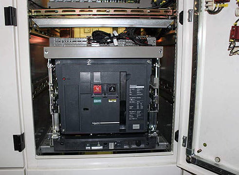
Retrofit:
An example of retrofitting could be upgrading a feeder MCCB circuit from 400A Thermal Magnetic MCCB to 630A with an Electronic Trip. This would be done for additional load to the building and also provides better electrical coordination between control panels. Care and consideration of the BSEN 61439 standard needs to be taken when doing any retrofits to existing panels.
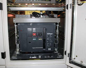
Refurbish:
This option means restoring existing equipment to its original condition and performance specification. This option is “age” driven as there is often limited access to the original manufacturers’ materials and documentation. However, a refurbishment can, in some instances, enhance the ratings and performance of the equipment supplied.
A refurbishment will involve a maintenance sweep of all parts (inspection, cleaning, and lubrication of parts, adjustments, and circuit breaker tests) with damaged parts also refurbished or replaced.
+971 52 386 0547

Phone Number:
+971 56 567 4149
Email Address:
Location:
Al Rumhi Building, Office No. 203-A3, Al Muteena Dubai, United Arab Emirates
Quick Links
Copyright © 2024 Neutral Ground Technical Services. All rights reserved.
Mon-Fri: 9am-5pm
Timings:
+ Support